Questions, Answers and Downloads
The DIY design download section has been removed.
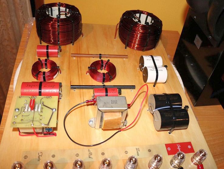
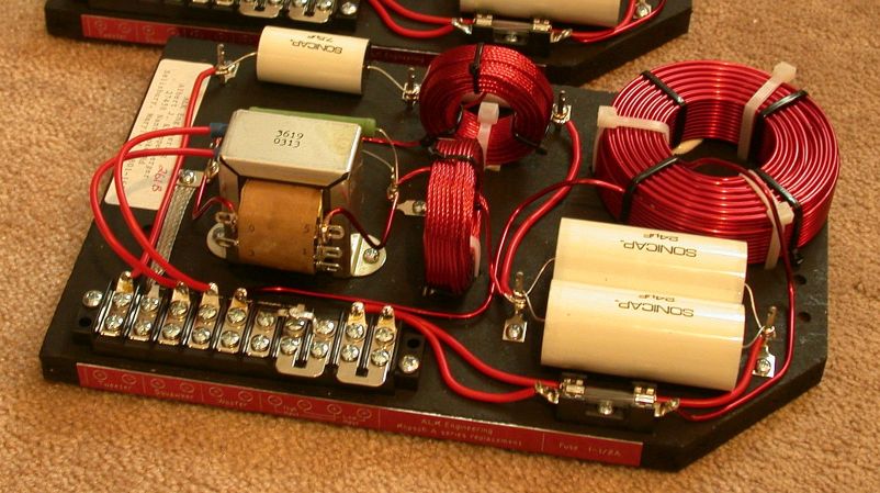 The real McCoy!
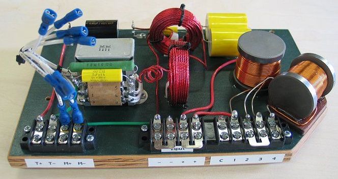 Enlarge Knock-off #1
 Unfortunately, because of one unscrupulous vendor who has seen fit to adopt my designs as his own claiming:
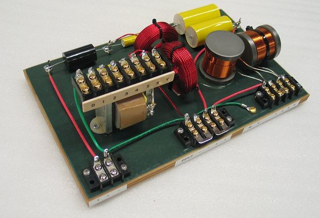 Enlarge Knock-off #2
This kind of "little changes" are not made to improve on a product but rather are to justify the theft of another person's creativity. The statement itself is clear evidence that he is doing just that!
Another big reason for not supporting DIY projects is the difficulty of determining who is really qualified to build crossover networks and those who believe they are but really are not. There is a lot more to it that just being able to solder!
For example, here is what a totally incompetent builder will do even to a kit which includes step-by-step instructions! One reason I no longer offer kits. I don't want my name associated with this sort of mess!
 Enlarge MESS
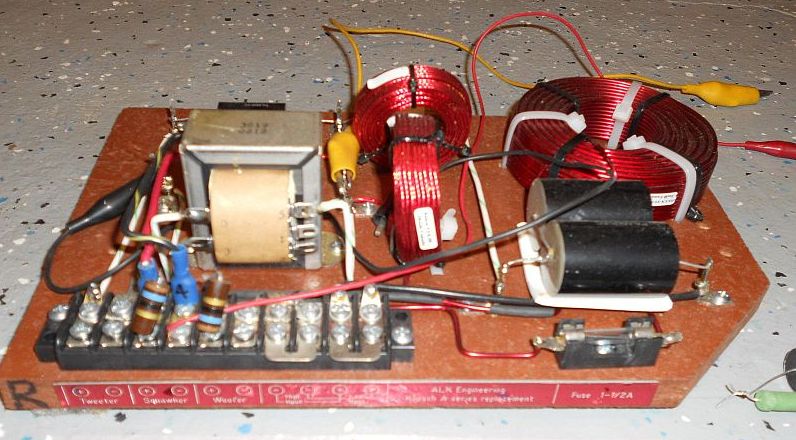
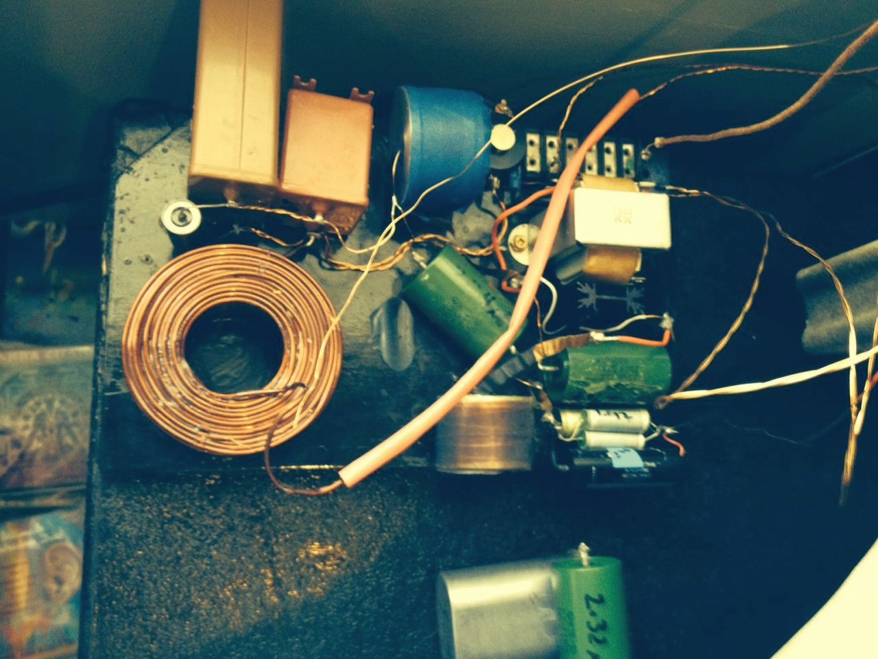
 Here's another example of what I want to avoid. He takes my design and decides to make a showpiece using the kind of layout techniques used back in the 1930 era! It looks like an engineering prototype "breadboard" done to verify that a design works before production! He believes he knows more about what parts should be used in my designs than I do. He even goes so far as replace the foil resistors in my tweeter attenuator with foil resistors (??) and proclaims how much of an improvement it makes. This is a clear example of what I call "O-D"ing on placebos! If you want something to sound better, IT WILL! I don't want my name associated with it in any way!
 Enlarge breadboard
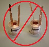
Here's one that is to horrible to describe!
 Enlarge
 ========================
Since I have learned that another vendor that I foolishly helped has claimed authorship of one of my designs calling it the "Super X", I am willing to share it with the DIY community. It was initially called the "Super AA" and was intended to be an economical rework of the Klipsch "AA". It changes the part values in the tweeter filter and adds an inductor and a resistor. The original T2A transformer of the AA was retained but it could be replaced with the Crites 3636 to give you 1 dB attenuation steps.
 Enlarge
The short answer is
Designing a crossover network, even if you have the specification sheets on every component is not easy. It requires that I have the COMPLETE speaker, in the cabinet, for testing. Here is a Klipsch forum thread describing the development of the network for the Klipsh Forte I. It should show you what is involved. Read more.
Extreme-slope crossover networks
A paper describing crossover networks similar to those shown below having slopes on the order of 120 dB / octave in a Belle Klipsch is downloadable here. The article explains their benefits which are improved stereo imaging and a widening of the "sweet-spot". The article also investigates such factors as filter ringing, group delay, driver interaction and time alignment. (by Al Klappenberger).
 "A case for extreme-slope crossover networks" (Size 4.3 Meg)
The short answer:
To the
A paper explaining the theory behind the use of an autotransformer and swamping resistor to allow adjustable attenuation of drivers in a crossover network.
(by Al Klappenberger)
"The Swamping resistor"
The short answer is:
The short answer is:
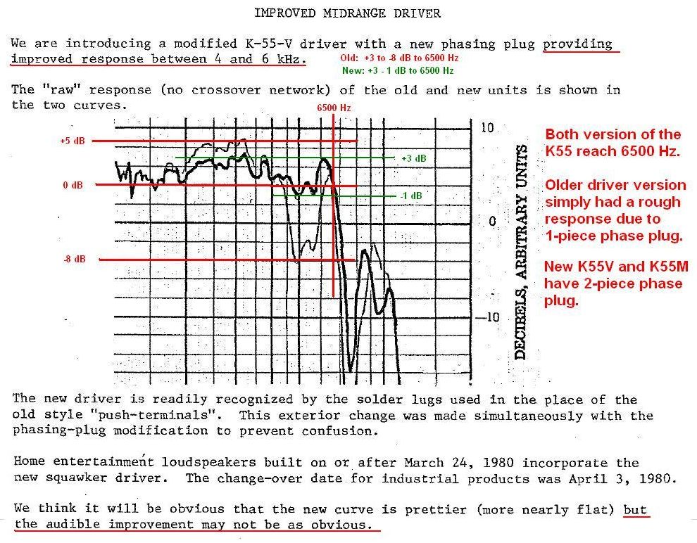
You may have heard that moving the crossover from 6000 Hz down to 4000 will improve the sound. This is true only if you retain the stock K400 mid-range "squawker" horn. The speaker simply sounds better because the tweeter is doing the work rather then the drastically outmoded K400 "headache maker" horn! The horn itself (not the K55 driver) should be replaced with a modern wood tractrix horn. You should do this
Another reason not to move the crossover down is the lower limit of some stock K77 tweeters will not handle a 4000 Hz crossover. The is particularly true of the round-magnet AlNiCo K77. It would require replacing the tweeter, which should be the last item on the upgrade priority list. The K77, especially the later square magnet version, is not a bad tweeter!
Here's another key into PWK's thinking: He always wanted a 2-way Klipschorn. That clearly tells us he wanted a single horn to do everything above 400 Hz. Not a crossover at 4000 Hz. or 6000 Hz, but INFINITY! No tweeter at all!
ALK networks are built using capacitors most appropriate for their particular function in the network. I do not make substitutions.
My guidelines are these:
- Quality name-brand metalized propylene capacitors in the "forward signal path". That is, capacitors in "series" that you actually listen through. This will usually be highpass filters.
- Solen "FastCaps" in "shunt" locations which function to bypass sounds that are to be stopped by the filter. These will be wired to common ground in lowpass filters.
- Capacitors are only acceptable that have low loss. Loss in any capacitor gets less at low woofer frequencies. This allows the use of "Mylar" types in woofer filters.
- Capacitors connected directly to an inductor to form a "notch" can be higher loss because the inductor determines the loss of the total circuit. Inductor loss is easily 10 or more times that of capacitor.
- Filters that are properly designed require part values that are clearly defined by the design. I only use those that are less then plus / minus 5% of the value required. The Claritycaps I use are within 3%.
- I computer match capacitors in pairs with sets located at the same position in the left and right crossover.
I do not allow customers to choose alternate brands of capacitors for these reasons:
- To keep costs down and to make matched sets, caps of identical types are purchased in quantity. The more you have of a given cap the closed the matched pairs will be. A large quantity of +/-5% caps will usually yield pairs matched within +/-0.2% of each other.
- Poorly designed filters that have rough frequency response curves will be smoothed out by high loss components. Correct designs do not suffer from this problem allowing low loss components to reduce insertion loss increasing efficiency. Using capacitors with high loss, such as paper in oil types, simply reduce efficiency. ALK network designs do not need "crutches" like that!
- Often customers will ask for higher quality caps in an economy design which just runs the price up to that of a more advanced design which will have the better caps anyhow! This is particularly true of the "Cornscalla-Wall" network.
- Finding sources of alternate brand parts is time-consuming, expensive and often confusing!
Using a separate high-power solid state amp to drive the woofer and a smaller vacuum tube amp to run the midrange and tweeter is called "Bi-amping".
Bi-Amping has advantages, but if you are interested, you must do careful research to be sure you understand how to do it. It is very easy to do it wrong! We do make crossover versions that support Bi-amping.
Look here for a Klipsch forum thread on biamping a 3-way speaker.
The short answer is
Each part in a properly designed filter has a very specific value. In order to change the crossover frequency it is necessary to change EVERY part value. It's referred to as "frequency scaling". Doing this to an existing network leaves nothing left but the mounting board. You might as well start over and build new network!
In the case of 1st order (6 dB / octave) networks, the slope is so gradual that moving the crossover frequency accomplishes nothing. This is why they are "universal". The acoustic characteristics of the drivers overwhelm the electronic crossover frequency. It's just not worth doing!
- I order parts in quantity to keep costs down. This means I need to accumulate a list of customer orders before I can order parts. Each list becomes a production "batch". I compile the list while I am build the networks from the previous batch.
- I offer a wide catalog of networks which makes keeping quantities of expensive parts unique to only one design in stock impossible.
- I have no assembler to help me. I build every network MYSELF. To keep from going nuts I do not build in marathon sessions. I work in "steps" on each network set. For this reason I don't really know how long it takes to build a specific network type. I usually do one or two sets a week depending on the complexity of the design. ES networks take longer! The build time for gentle-slope networks is much shorter. While I build networks I compile the customer waiting list for the next batch.
- Each "batch" resembles a rotating cycle without a fixed time period. The timing depends on the number of orders in the previous batch.
- Some parts suppliers take longer to deliver than others. A production "batch" begins when all the parts are in.
- Some parts suppliers will hold up shipping items they have in stock until back-ordered items are available. Every shipment has to be evaluated to see if other parts can substituted, if partial shipments are justified or if I can get the other parts from other sources. It can get very confusing!
- I have no heated area to make the network base boards. I cut them in my garage and paint them outside. I am often slowed down by the weather. ALK Engineering is a home-based business.
The short answer is
The phenomenon of "break-in" is a myth. It's your ears that is breaking in! When you make any change in your speakers you will invariably change your perception from normal listening to "critical listening". This is when you stop listening to the music and start listening to the speakers. When you do this you will hear only what you want to hear to the exclusion of all else. Gradually, over time, you will switch back to listening to the music again. THAT is the break in period in action! The crossover networks have not change at all. You are simply getting used to the new sound.
The short answer is
Providing a stereo amplifier with a constant 8 Ohms load is not actually required. Very few crossover networks designed by others are constant impedance. The stock networks for Klipsch Heritage speakers is all over the place. Some cause 8 Ohms speakers to look more like 70 Ohms in the midrange! The actual merit of a constant impedance is that it is the mark of a properly designed filter. This is a lesson learned through years of experience designing filters a microwave frequencies. With stringent requirements on "return loss" at microwave frequencies you quickly learn to do it correctly. There is simply no good reason why a network should NOT have a constant impedance! The fact that good amplifiers with high damping factors can handle bad loads is no more a reasonable argument for poor designs then a highway engineer would claim that a road should have lots of curves and bumps simply because cars have steering wheels and shock-absorbers!
Another way to put it is that a network that provides a constant impedance will sound better, not just directly because it loads the amp with a constant impedance, but because it is a correctly designed network.
On the other hand, if you have an amplifier with poor damping factor, like a 5 Watt SET, It will operate much better if it sees a constant impedance load. The frequency response can actually follow the load impedance curve.
 The short answer is
The measure of quality of an inductor is "Q". It is a measure of internal loss at a given frequency and is defined as X / R or inductive reactance divided by equivalent series resistance. The greater the Q, the lower the loss. In a crossover filter, the Q must be optimized at the crossover frequency. That is the point of maximum "stored energy" and the point of peak "group delay". This is were component losses do the most damage. The plot of the tweeter filter of the ES5800 network shows a considerable "sag" at 6-7 Khz (red trace) compared to the same filter with a perfect inductor (green trace) but not so much at 20 Khz.
The red plot was assuming a constant inductor Q of 45 at all frequencies. In the real world, the "sag" at 6 KHz would be more exaggerated because the Q of the Litz inductor comes to a peak at 20 KHz. The foil inductor would be worse yet since it's Q peaks at roughly 50 KHz!
The chart below shows the "Q" curves of several inductor types wound of solid wire, Litz wire and foil. The chart also shows the frequency range covered by the tweeter (6-20 KHz.). It is over
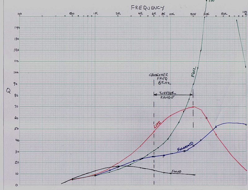
Also: The plot also tells us that inductors used in woofer filters should be wound of SOLID wire.
To make matters worse for the foil inductor, its inductance value is not stable with frequency. This plot compares a 0.20 mHy Litz inductor to a 0.20 mHy foil inductor. The foil inductor is 5.5% low in value at 6 Khz. This is more than enough error to mess up a correctly designed filter! The Litz inductor measures 0.2 mHy at all frequencies.